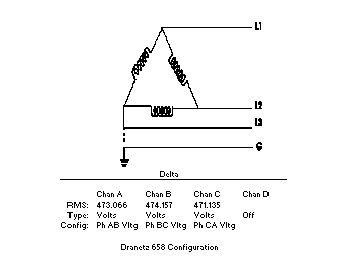
A plastic extrusion manufacturer in the mid-West had a 480V delta feeding a plastic extrusion machine. The ASD-driven synchronous motor in the extruder had a half-wave bridge rectifier circuit to provide excitation voltage to the pole coils.
Diodes on the half-wave bridge exciter circuit were blowing out, and the filters to the SCRs were being damaged.
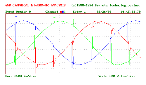
Three channels of the voltage supply feeding the extruder were monitored for just two seconds before enough data was collected to determine the cause of the failures. As shown in Figure 1, a burst of transients would occur three times a second. The RMS voltage did not change significantly during these transients.
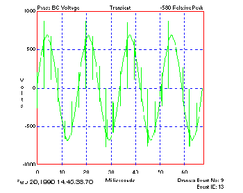
Closer examination of the waveforms showed that the transients were actually a repetitive series of voltage transients, occurring six times a cycle on all three phases. An example of the voltage waveforms for one phase is shown in Figure 2.
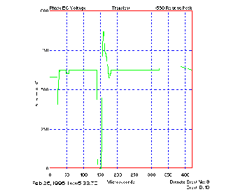
These repetitive voltage transients are referred to as voltage notches. The maximum voltage of the transient could produce damage, and the voltage notches that cross the zero axis could result in zero crossing errors. Closer examination of the transients is shown in Figure 3.
Analysis
The following were calculated values of this voltage disturbance monitoring period:
- Number of transients: 192
- Amplitude: -580 volts
- Worst Absolute amplitude (from zero crossing): 864
- Rise time: 1.0851 microseconds
- Frequency (1/4*rise): 230.4 kilohertz
- Number of zero crossing errors this frame: 146
- Worst zero crossing width: 61440 microseconds
- Worst zero crossing delta voltage: 168 volts
- Worst notch area: 0.021475 volt-seconds
Transient Analysis
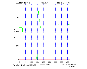
The absolute amplitude value confirmed the cause of the damage to the diodes, as this voltage exceeded the ratings of the diodes in the half-wave bridge. The very fast rise time and equivalent frequency greater than 100KHz of the transient indicates that the source of the transient is relatively close to the measuring point. This would indicate that the origin of these transients was an electronic switching load such as a bridge rectifier used on many electronic motor drives. The transients on other phase voltage channels were not the same polarity, but occurred at relatively the same time, as shown in Figure 4.
Zero crossing errors can cause timing problems with phase controlled and electronic loads. Clocks can run faster and power electronics, such as SCRs and switching diodes, can misfire and be damaged. Notching can also trip protective relaying, stress power electronics, and cause excessive heat in motors and transformers.
Harmonic Analysis
The harmonic analysis in Figure 5 of the initial waveform event of Phase BC Voltage shows the channel’s total harmonic distortion was 11.2%. The highest harmonic was the 2nd, at 8.3%. The high values of even harmonics is attributed to the half-wave rectifier, whose Fourier expansion is made up of solely even harmonics.
Repetitive voltage transients are usually caused by phase-angle controlled loads, such as three phase converters. A voltage notch results from two phases being momentarily short- circuited during the commutation period. In this case, they were creating by the ASD drive itself, which converts the AC to DC and then back to AC to control the motor’s speed and torque. The half-wave bridge used as the voltage exciter was the source of the abnormally high even harmonics.
The solution employed was to place MOVs with appropriate clamping voltage across the diodes in the bridge to prevent their destruction. Though not used at this site, special filters, such as certain line tracking filters, can be used to alleviate zero crossing errors. In addition, power conditioning devices, chokes or special filters could be used to “fill in” the notches and smooth out the waveform.


