Elevator control panels for the lower zone mid-rise elevators were on the nineteenth floor of a forty story office building in a large midwestern city. It was fed with 480V transformer on the same floor, with the feeders to the controls rated at 800A. Excessive noise and vibration of the feeder wires and conduit were noticed on a number of upper floors.
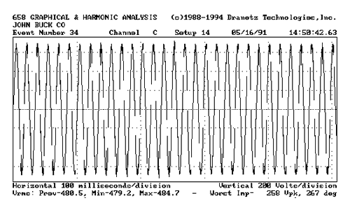
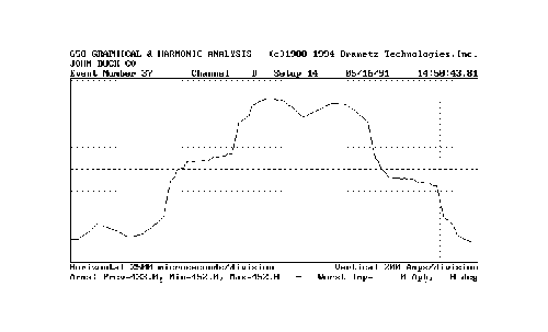
Monitoring was done on at the service panels on the 19th, 25th and 37th floors. Different combinations of the three voltages and three currents were monitored for only a short duration before the source of the problem became evident. Figure 1 and 2 below show the time plot of voltage and current, respectively, on one phase, which were representative of all of the phases.
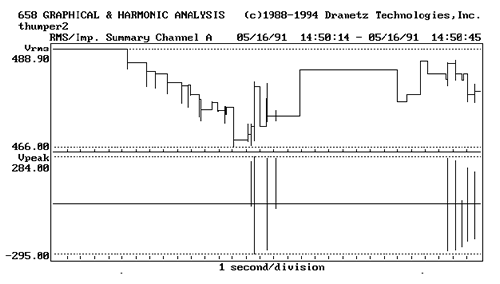
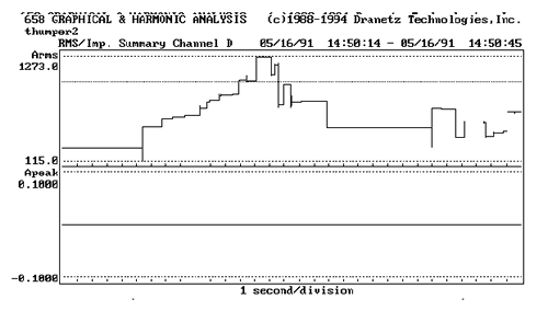
As the current values increase, a corresponding decrease in the RMS level of the voltage is observed. The maximum current is over 1200A on the 800A service.
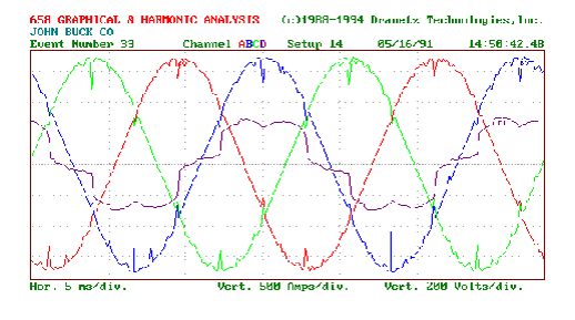
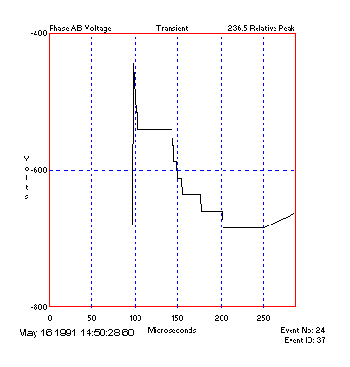
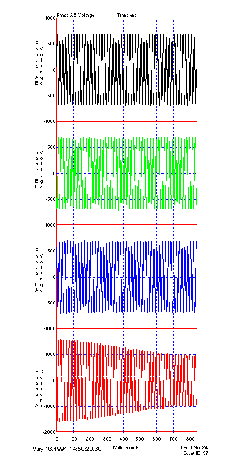
The voltage transients during this 40 second window were nearly 300V. Closer examination of these transients can be seen in Figure 3 and 4. Notice how the voltage notches appear in the same position on the wave of each of the phases.
Analysis
During one 20 second measuring period, there were 77 transients recorded.
- Amplitude: 236.5 volts.
- Absolute amplitude (from zero crossing): -684.
- Rise time: 1.0851 microseconds
- Frequency (1/4*rise): 230.4 kilohertz.
Though there was no corresponding transient in the phase current to suggest the origin of the transient, the phase current was observed to be switching at the same time. The transient frequency was greater than 100 khz suggesting the origin of the transient was local to the monitoring location.
There were also a number of zero crossing errors observed on the voltage channels.
The worst zero crossing width was 277.6 microseconds and the worst zero crossing delta voltage was 28.5 volts.
Voltage Notch Analysis
Voltage notches were the most prevalent type of event observed. As noted, these occurred at the same phase position on all phases and corresponding to the current waveform. A one second monitoring period noted 3026 such notches, with a worst notch area of 0.42159 volt-seconds. The depth of the notch was most severe on the voltage phase corresponding to the current phase that had the step change in current.
Harmonic Analysis
The voltage channels’ total harmonic distortion was typically under 4%, varying under diffent loading. The fifth harmonic was the predominate one, at 2.4%. This corresponded to the current harmonics, as shown in Figure 8 for the current waveform in Figure 7.
Probable Cause
The voltage transients, whether appearing as notches, zero crossing errors, or just unipolar transients, were probably the resulting of the electronic switching load, such as in elevator controllers. While these were quite excessive, the amplitude and width did not seem to be severe enough to cause malfunction of the elevator controls. Continued operation in this manner may eventually lead to such failures. Notching can cause timing problems with phase controlled loads, trip protective relaying, stress power electronics, and cause excessive heat in motors and transformers. It often takes power conditioning devices , chokes or special filters to “fill in” the notches and smooth out the waveform.
The voltage transients and the voltage fluctuations were caused by excessive current draw through the inadequately sized and supported service. This also produced the “thumping” sound, as the magnetic fields generated by the three phases tend to push the cables apart. A general rule of thumb is that the conductors will jump when the current is 120% of maximum rating. In this case, the current levels peaked at over 50% of rating, but were within the steady-state rating of the system.
The elevator manufacture recommended that the size of the feeders from the transformer should be increased by at least 50% for both of the elevator controllers. Caution should be used that the conduit has adequate size to accommodate such, in accordance with NEC. The utility engineer noted more correctly that the problem was the result of the conduit being inadequately supported to the walls.